
français
Mesure directe du débit massique. Précision : ±0,1 % à ±0,2 % pour les liquides ±0,5 % pour les gaz Mesure de la densité, de la température et de la pression Large plage de mesure jusqu’à 100:1
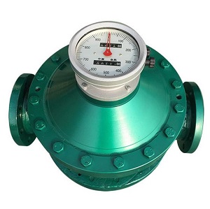
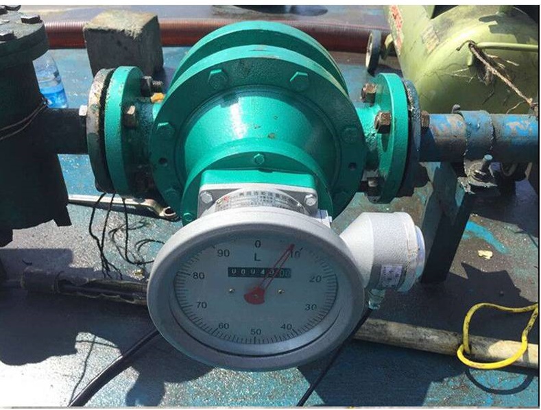
Pourquoi les débitmètres volumétriques peuvent être utilisés pour les carburants et les huiles ? La mesure du débit volumétrique des carburants ou des huiles fait référence au diesel, aux carburants à base de pétrole, au kérosène, au mazout domestique, au
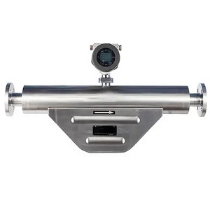
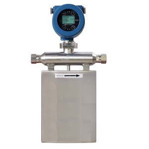
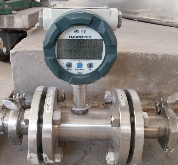
débitmètre Coriolisest un choix parfait de mesure du débit de fioul Le débitmètre massique Coriolis se compose généralement d'un tube de mesure et de deux capteurs qui mesurent les forces de Coriolis générées par le fluide lors de son écoulement dans le tube. Ces forces sont directement proportionnelles au débit massique du fioul, ce qui permet des mesures très précises et fiables.
Les débitmètres massiques de fioul sont capables de mesurer une large gamme de débits, des plus faibles aux plus élevés, et peuvent traiter différents types et viscosités de fioul. Nous proposons un large choix de capteurs de débit massique, avec une plage de mesure allant de 1 g/h à 1 000 tonnes/h. petit capteur de débit tailles de 1 mm à débitmètre à huile de grande capacité comme les débitmètres d'huile de 10 pouces, ils sont également conçus pour résister aux conditions difficiles que l'on rencontre généralement dans les environnements industriels, tels que capteur de débit massique d'huile haute température , débitmètre massique haute pression, et débitmètre massique pour fluides corrosifs et produits chimiques, mesure du fioul haute pression, mesure du fioul à haute viscosité .
 |  |
| |
 |  |
 | |
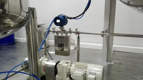
1. The coriolis mass flow meters are working based on the vibration working principle. So it is the best that there will be no vibration on the installation place. And the strong support of the installation pipelines of the coriolis mass flow meters is very import. If the vibration cannot be ignored, it is suggested to use the soft tube connection. And the connections pipelines and the mass flow meters should be on the same axis. Please do not add additional force on the mass flow meters, other wisethe accuracy of the mass flow meters might be affected.
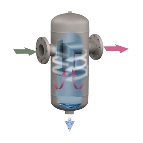
2. If the percentage of the gas in the measured oil fuel is high, then it is a must to install the gas- liquid separation tank on the inlet of the coriolis mass flow meters.
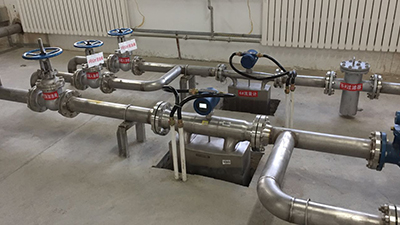
3. The throttle devices, for example the flow control valves should be installed on the outlet of the mass flow meters.
4. The mass flow meters should be installed away from the outlet of the pumps. Especially for the Dual pumps, if the installation distance is too close, then the measured flow rate could be affected, which is fluctuated.
5. If measuring high temperature oil or it is required to keep warm of the measured oil, Please keep distance between the inner tubes of the heating jackets or the heating tubes with the housings of the sensor. We factory also provide the heating jackets along with the mass flow meters, for example the heating jackets for steam or transfer oil. Please specify that you need heating jacket for flow meters to silverinstruments.com
6. The measured oil should be on the suitable flowing status. If under the local environment the flowing status of the liquids is not suitable, then it is suggested to improve with other methods, for example to modify the temperature of the liquids ( increasing / decreasing the temperature of the fuel oil to make sure the measured liquids are in the proper flowing status.
7. Installation direction: please make sure the flowing direction of fuel oil should be the same with the direction marks on the nameplates of the coriolis mass flow meters. Otherwise the accuracy of the mass flow meters could be affected.

8. Please make sure the series numbers of the mass flow transmitters and the fuel oil flow sensors are one -to-one corresponded to each other. It cannot be easily changed. Otherwise the accuracy of the mass flow meters could be affected.
9. If the fuel oil mass flow meters are installed on the outdoors, then it is the best to install the rain shelters for the mass flow meters. And please make sure to keep both the front and back covers of the mass flow meters tightly closed. And please make sure that the electrical interface is sealed well to prevent the waters flowing inside the transmitters.

10. It is suggested to use the normal working flow rate higher than the 1/3 of the standard flow range of the mass flow meters. And it is suggested that the actual minimum flow rate should be higher than the 1/10 of the standard flow range of the mass flow meters. If it is in special situation, please communicate with silverinstruments.com, As we have our own R&D team, we can customize the mass flow meters based on your own special requirements, to make sure that we can meet with the requirements of the users of the usage range.
The integration of the Coriolis Mass Flow Meter has been connected and installed before the delivery.
The separated transmitter and the sensor are connected by the special connection cables and connectors. If the separation installation of the transmitter and the sensor is required, please contact us in advance before placing the order. The maximum length should not exceed 300m.

24V + \– 24VDC Power Supply (Current should not less than 500mA)
Fo + \– Frequency Output (instantaneous mass flow or volume flow)
mA + \– Current Output (instantaneous flow or density optional)
(HART + \–) HART
485A \485B RS-485 Communication (Baud Rate: “9600”, Address: “1”)
The zero point calibration is required after the Coriolis Mass Flow Meter installation. Please fill in large amount of measured medium for 10 minutes before the zero point calibration.
The zero point calibration is used to provide the benchmark of the flow measurement. The zero point must be processed after the first-time calibration or re-installation. Please make sure firstly it is required to turn off the stop valve at the exit of the mass flow meter, and then turn off the stop valve at the entrance. And make sure the liquid fulfilled the sensor is comparatively at the stationary state during the calibration. The detailed operation methods are as below video shows:
Trouble shooting for Coriolis flow meter
Symptom | Failure Reason | Solution |
No display | Check whether is 24VDC power supply is normal | Make sure 24VDC is working normally |
Fluctuation of flow rate measured is large | Whether there’s strong vibration of the line connected to the sensor | Adding support or switching to hose connection |
Could not enter the measuring interface after the boot | Do not connect with the sensor | Check the cables, and make sure they are connected to the sensor properly |
Zero Point Drift is large | The installation of the sensor has stress | The connecting line and the sensor interfaces should be at the same axis |
Attention: (0-10)KHz and (4-20)mA output signal is already with the power supply. It is forbidden to connect with other external power sources. Otherwise the damage of the mass flow meter could be caused.
nous vous répondrons dans 24 heures..